Repair of the bellows of a swell shutter engine


July 2017
Overview:
- A conventional swell engine
- Swell shutters individually governed by bellows
- Operation and removal of the bellows
- Repair of the worn bellows
- Tracing and rectifying faults swell engine
A conventional swell engine
All romantic organs have at least one division (played from the second or third manual) of which the organ pipes are placed inside a more or less sound insulated space: the swell box. The sound intensity is governed by ten to thirty shutters, made of thick wood, that can be opened by the organist by pushing his right foot on the swell pedal. In most organs, swell shutters are connected to each other via wooden rods and a rod to the swell pedal. Here you see the swell shutters of the Saint-Anna organ I dismantled. (The door in front is of course normally closed.)

If the action is not direct (mechanical) but electrical, a 'swell engine' is used that pushes the rod by inflating several bellows, as in the organ above (not visible).
Swell shutters individually governed by bellows
The pipework of the positif manual of the Hilboesen/Pels organ of Saint-Boniface (Sint-Bonifatiuskerk) in Alphen-on-Rhine (Alphen aan den Rijn) is also placed in a swell box. The sound intensity is governed by twelve shutters, made of 40 mm thick oregon pine. However, in the Boniface organ, built in 1939 by Bernard Pels of Alkmaar, the twelve shutters are moved individually by a bellow. Every shutter is fully open or fully closed. The intensity of sound is not determined by the opening angle of all shutters together, but by the number of shutters fully open. This has advantages and disadvantages, but the crescendo effect is certainly not worse compared to the conventional 'linear' system (as I can testify as this is the organ I played on for more than 25 years).
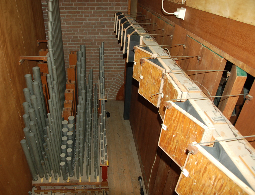
The bellow of each swell shutter is normally closed and a spring pulls it so, in order to open the shutter if the organ is switched off. This ensures that the temperature of the organ is homogeneous and the swell division is not getting out of tune compared to the rest of the organ. If the organist closes the swell pedal with the heel of his right foot, an electrical contact is made, a magnet is energised and a pair of disc valves is opened so that organ wind is inflating the bellow. Via a steel wire, the shutter is pulled to close.
(By the way, the green felt on the upper (and lower) side of the shutters was applied by myself some thirty years ago, when I was organist of this church, in order to improve the swell effect by improving the acoustic insulation of the closed swell. This and other measures worked out very well and the crescendo and in particular decrescento effect of the Saint Boniface organ were amazing.)

The swell pedal is connected to a contact rail in the console via a wooden rod, seen directly to the right of the centre of this photo. By moving the rod, ten contacts are closed or opened (numbered). The swell division has twelve shutters, so?! The four shutters opening last are switched in pairs of two. That's smart, because the dynamic difference between 8 open and 4 closed shutters is almost negligible compared to 9 open and 3 closed. On this photo, we see the general combinations in the centre, the soldered contacts to the organ at the left and the new panel for the detached choir console on the right.

More details of the construction below, if I show the work done on the swell assembly.
Operation and removal of the bellows
The bellows are made using rubberised canvas linen, glued onto the edges of the wooden bellow boards. The folds consist of thick cardboard glued onto the linen. Because there were no laths to secure the linen to the boards, the glue had come loose and the bellows were severly leaking. This not only caused noise, but more importantly the swell dynamics were severly limited (actually the swell effect was close to zero).
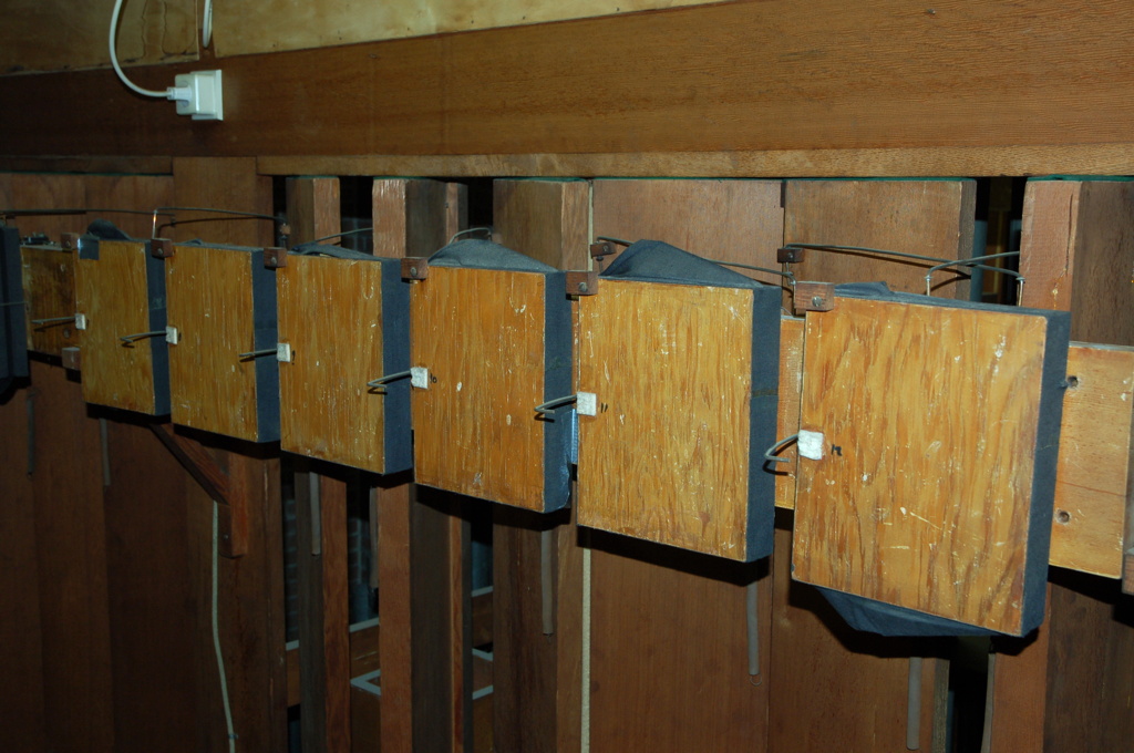
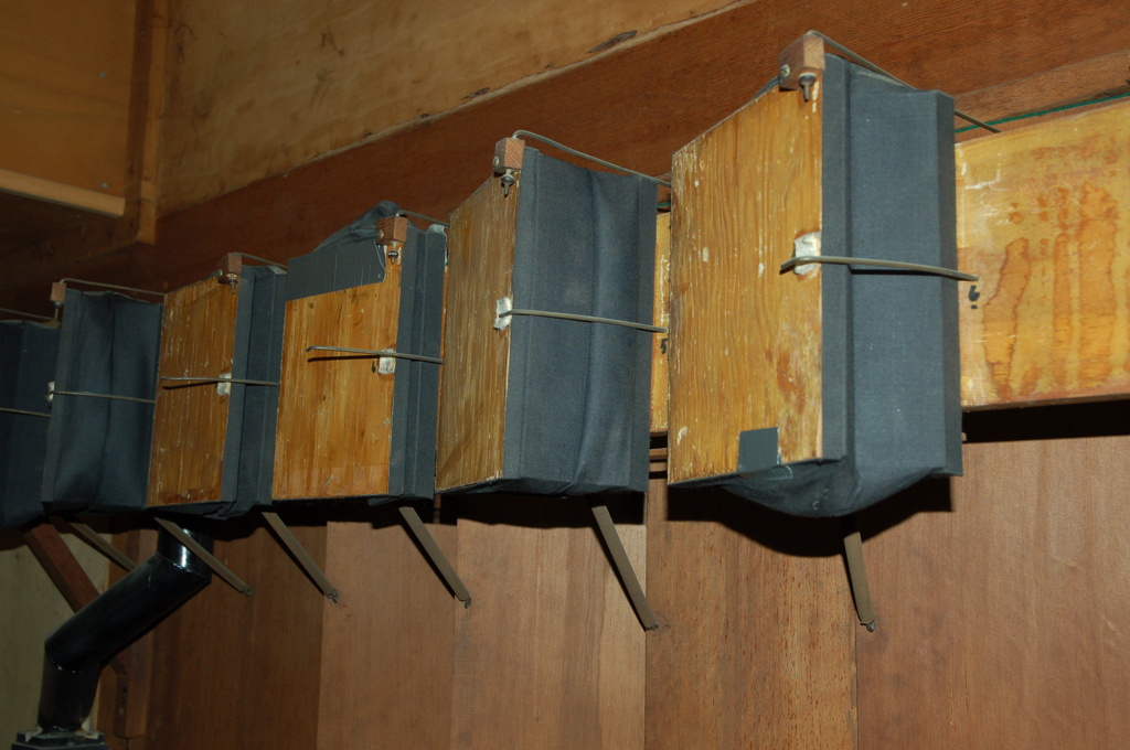
It was not easy to determine how to remove the bellows or the swell engine as a whole. In the end, the bellows turn out to be fixed to the action windway with three screws, from the inside! In order to reach the screws, the closing panels had to be removed, from the back of the windway, near the swell shutters. Some shutters were removed and doing some acrobatic climbing was inevitable.
One shutter removed, spring detached. Rear panel of the windway removed. The pneumatic action is visible. Two shiny screws can be seen.

The pneumatic pistons inside the windway can be seen after the panels have been removed. Also visible are the horseshoe magnets and two of the screws unscrewed. And the hand of my assistant.
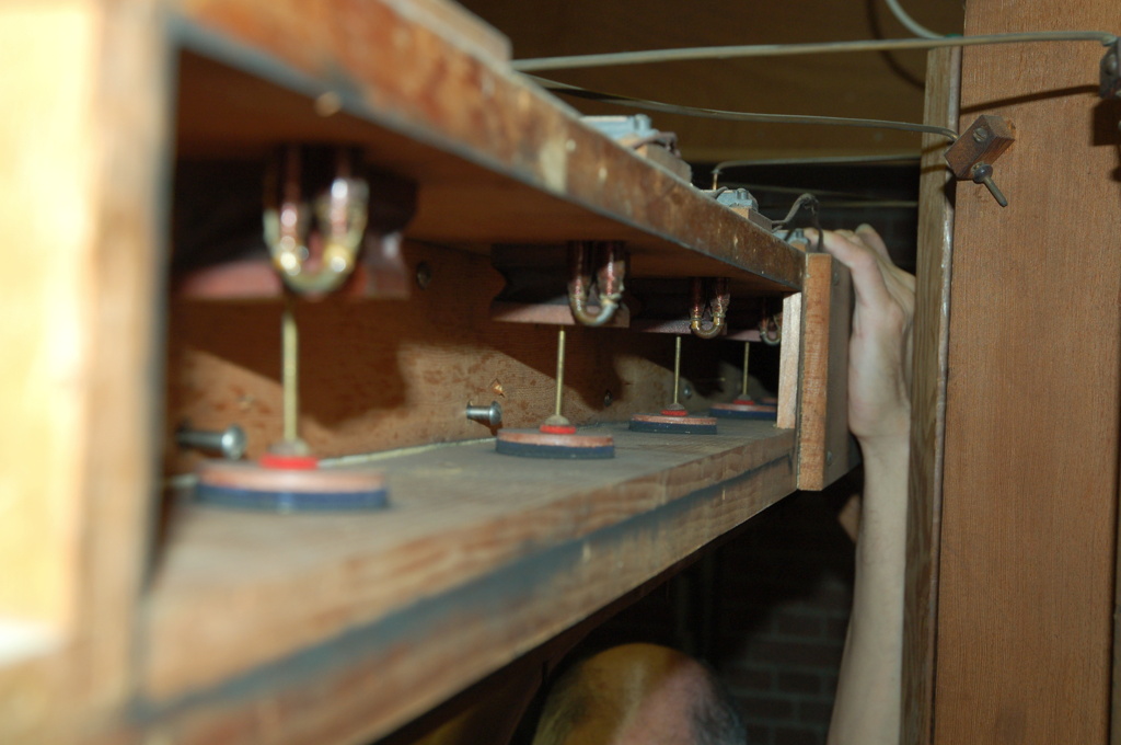
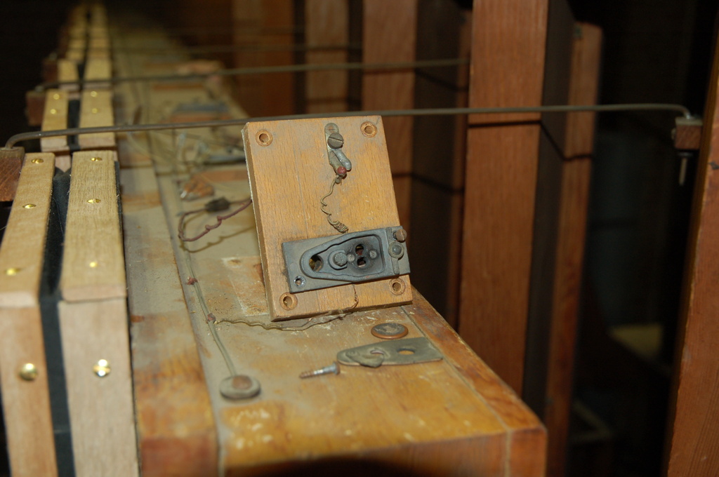
The operation of the mechanism can be explained using the photo below. Its level of complexity is typical for the electropneumatic or pneumatic organ action. As said above, normally the bellow is folded in, also by the action of a spring, keeping the swell shutter open. If the electrical contact is closed by movement of the organist's feet on the swell pedal, the horseshoe magnet is energised. It attracts a small steel disc, closing a small windway to a little square bellow glued to the roof of the channel (the dark brown thingy). Now the wind pressure in the large windway presses the small brown bellow empty (in the surrounding air) and the steel rod connected to the brown bellow is lifted. It opens the large circular valve on the bottom of the windway. A similar disc valve under it closes the way to the surrounding air. Via the open disc valve, pressurised organ wind is flowing in a small channel and this in turn inflates the large black bellow to which the shutter is connected, as seen above. So the action in fact consists of five levels …
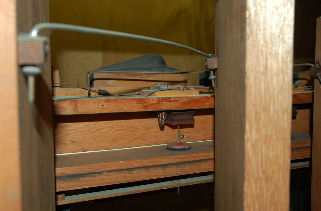
The horseshow magnet attracts a small circular steel disc, closing the two tiny cirular windways.
Repair of the worn bellows
The twelve bellows were taken to the workshop. In general, the linen, dating from the 1984 restoration, was in good condition, it was only separated from the bellow boards. Of some bellows, the folding edges were worn out and some of the cardboard 'folds' had also separated from the linen. It was decided to renew only the severly worn out linen, to re-glue all linen, and to apply reinforcement patches.
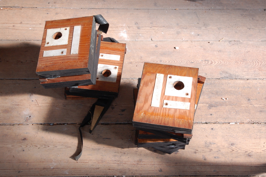
The cardboard 'folds' that keep the bellow in shape had separated from the linen in some instances.

Sometimes only the linen needed to be re-glued to the boards. In all cases reinforcement linen patches were applied, seen in the upper middle.
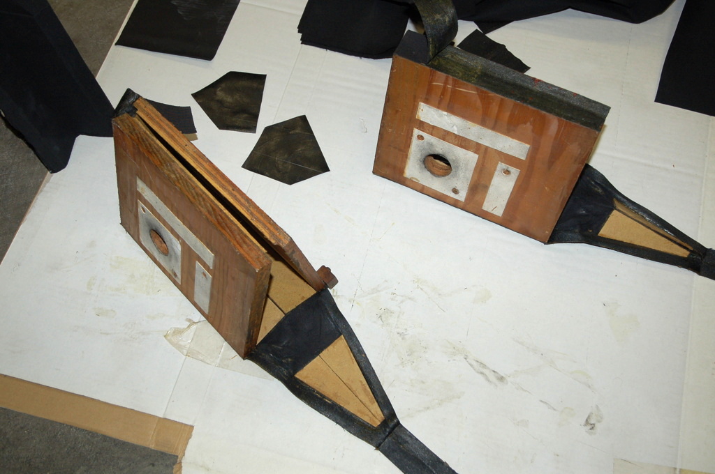
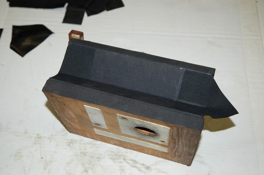
The bellow is ready.

Some bellows had to be re-covered completely. Here you see the removed linen (below) and the new patch of rectangular linen to which the cardboard folds are glued (middle).
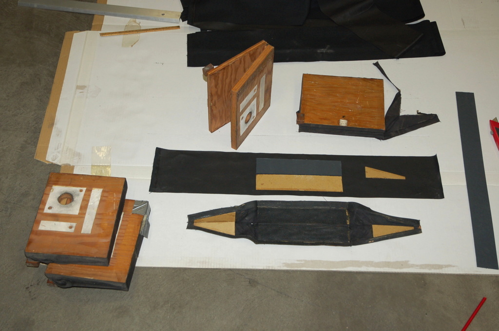
After glueing, the linen is cut to fit.

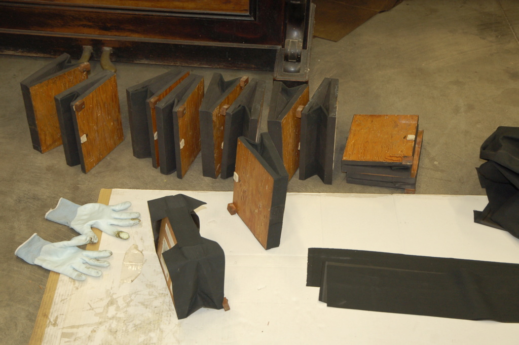
It is wise to secure the glued edges of the linen cover to the bellow boards by fixing laths to the edges. In 1984 for one reason or another, this was not done.

Then the twelve swell bellows were screwed to the windway and swell engine. The swell engine was closed, springs and wires were assembled etcetera. My mate Koos is assisting. It looks like he is preparing to read the Lecture from the Bible ![]() Mind the stole …
Mind the stole …

This is the result.

There are two bellows still not functioning. The probable cause is different for both. As we wait for approval to rectify this, these two bellows were fixed in their closed position, as the dynamic effect is at maximum then (from closed to slightly open is more effective than from almost open to fully open).
Indeed, the swell dynamic range is very large again! This was a rewarding job.
Tracing and rectifying swell engine
December 2017
The swell engine is, as described above, working by means of twelve swell bellows that are either fully open or fully closed. After the renewal of the leathering of the bellows, two bellows remained non-functioning. Repair is only possible if the fault can be traced down and this can be difficult. Of course a good understanding of the operation of the full swell engine is crucial. At the start of this follow-up assignment it is not yet clear how complex this will get and how much work the recovery will entail.
The first fault: a leaking bellow … but another as one might think
In the above, the rather complex operation of this swell engine was explained. We start tracing down the faults by measuring whether there is voltage on the horseshoe magnet if all shutters are closed. That is the case, so the fault is not in the electrical circuit, but in the mechanism that operates his shutter.
Now I noticed that this horseshoe magnet blows. The others do not do that. Last time I even took it apart. The steel disc that is attracted by the horseshoe magnet appears to move freely. So that is not the fault. Blowing could also be caused by wind coming from the windway to the horseshoe magnet. Normally this is not possible, because the wind circuit of the small operating bellow at the top of the windway (the 'brown thing') is not connected to the windway itself. That could be the fault: this small control bellow could leak. Note: this bellow is a different one than the pushing bellow that close the shutter and that was the subject of the above story.
After the windway was opened (a lot of work again: from the rear), I looked closely to the small bellow and press it empty with my fingers. Indeed it seems to leak. Then the bellow was detached from the ceiling of the windway and we indeed see that the leather is torn!
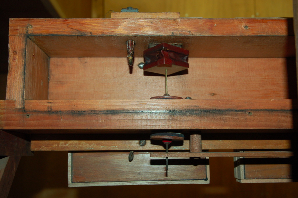

The bellow is re-upholstered with fine pneumatic leather, after the old upholstery, which has been deteriorated by the time, has been cut loose. After gluing, the leather is cut flush with the bellow surfaces.
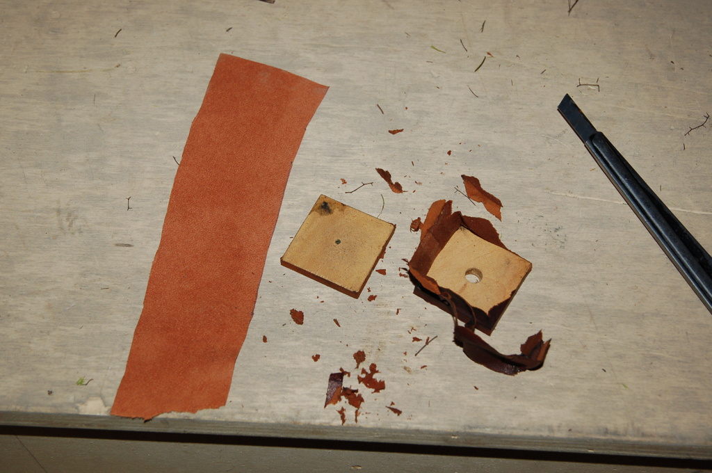

The bellow is glued to the ceiling of the windway and it is closed again. It turns out to work again!

The second fault: a bad contact … but where?
The second bellow that did not work, did not show voltage. But where in the circuit is the fault?! I started with the easiest place to reach: the console. For this it was necessary to figure out how the magnets are connected. It may even have to do with the electronics of the new connections for the second console on the church floor.
It appears that the conventional action in the old console is still fully operational and that the electronics that receive the signal from the second console are connected to the solder points where the cabling from the old console is connected to the organ. Moreover, after measuring it turned out that the swell shutters still work with the old console. With this, we know about where the fault can be found.
Below the interior of the old console from 1940. It all still works fine! On the left the connections of the cables to the organ on the contacts of the console. The colored cables have been added when the second console was connected. The electronics on the right are to translate the control signals from the console below to the 'old' organ. In the middle you see, among other things, the contact cam which is connected to the swell and that closes the contacts of the twelve shutters to closed them (there are ten contacts, two pairs of shutters are operated at the same time!).
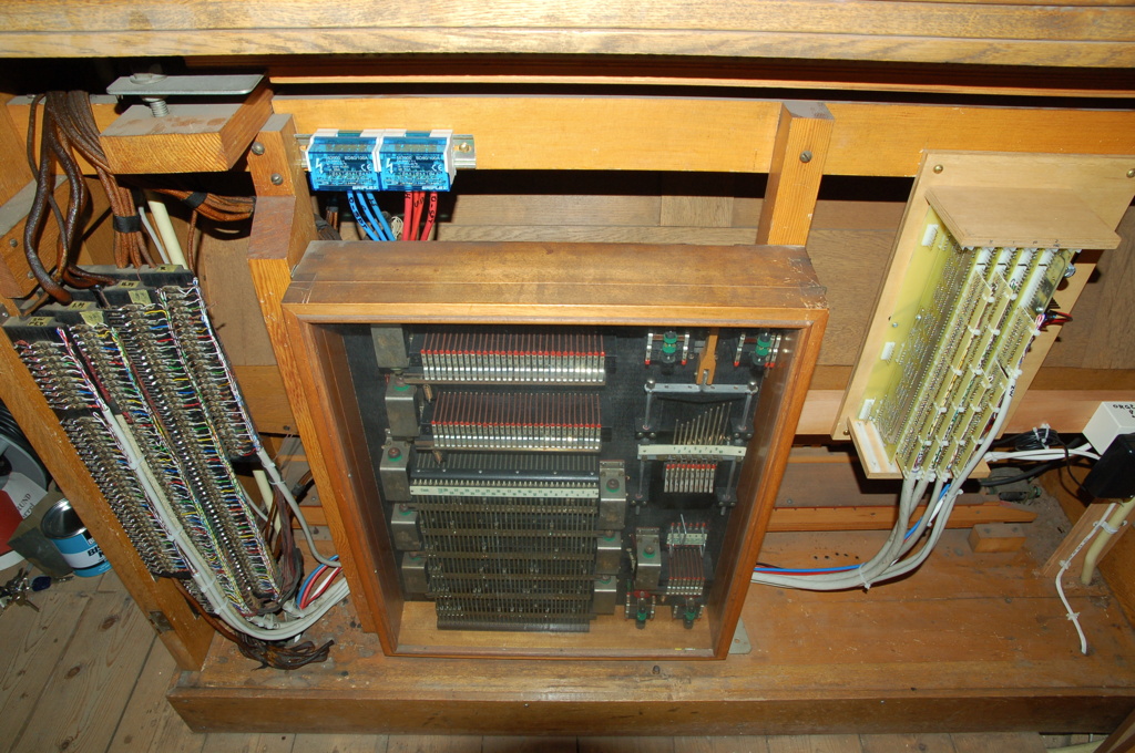
Once we have checked where exactly the faulty shutter is connected, we can trace further on. It turns out that when soldering the new console to the old contacts, using diodes to prevent current from looping back, the contact was badly soldered. I have slightly bent it here, so that the loose contact is more visible. Do you see it? It is the sixth diode from above.
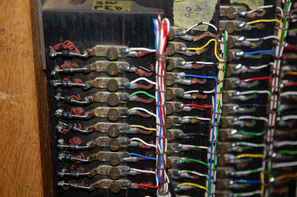
After I have soldered this connection again, this shutter is functioning again. This makes the entire swell engine operational again and one can once again enjoy the great dynamics of this swell.
Kind regards,
Rens Swart